
User Guide: Difference between revisions
| Line 106: | Line 106: | ||
*a) '''Neutral Model''': Neutral models are a generalization of the neutral landscape models introduced by Gardner, O’Neill, Turner, et al. The original neutral models only permitted two feature types; we have generalized these to any number of features. Essentially, a neutral model is a description of the characteristics (or constraints) of a pattern that are independent of other (i.e. external) ecological and abiotic patterns and processes. An instance of a neutral model is a single map (layer) that is produced using these constraints. We have also improved the manner in which contagion is computed during model generation (removing the high levels of horizontal bias in the Gardner et al. models). | *a) '''Neutral Model''': Neutral models are a generalization of the neutral landscape models introduced by Gardner, O’Neill, Turner, et al. The original neutral models only permitted two feature types; we have generalized these to any number of features. Essentially, a neutral model is a description of the characteristics (or constraints) of a pattern that are independent of other (i.e. external) ecological and abiotic patterns and processes. An instance of a neutral model is a single map (layer) that is produced using these constraints. We have also improved the manner in which contagion is computed during model generation (removing the high levels of horizontal bias in the Gardner et al. models). | ||
* | *:To produce instances of a neutral model, set up the constraints, as described below, and press the Generate button. When finished, the dialog can be closed with “Cancel”. | ||
*:[[Image:Neutral model.gif]] | |||
* | *:The following are the constraints that can be used to express a neutral model: | ||
**i) '''Width''': The number of columns (cells per row) in the neutral model raster. | **i) '''Width''': The number of columns (cells per row) in the neutral model raster. | ||
**ii) '''Height''': The number of rows (cells per column) in the neutral model raster. | **ii) '''Height''': The number of rows (cells per column) in the neutral model raster. | ||
Revision as of 21:12, 3 November 2006
Note: this conversion between the Word .doc and the Wiki is incomplete: please help
Documentation Version SELES v3.1
The purpose of this guide is to assist users of the Windows version of SELES. The SELES user interface is based on Windows NT, and runs best under Windows NT, Windows 2000 and Windows XP. It assumes that the models to be used have already been constructed. See the SELES Model Builder’s Guide and the SELES Scenario Reference for information on how to construct SELES models. This document describes how to use the SELES program to load in initial conditions and models and to run simulations.
Startup
After starting SELES, the user will be presented with the following interface. The operations available under each pull down menu are described in the following sections.

File Menu
The file menu has the following options.
- a) New: Creates a new view window with a viewname “Seles#”, where # is a number (numbered sequentially from 1). The underlying raster will be 100 by 100, with all zeros.
- b) New2: Creates a new view window with dimensions taken from a current view, and user specified bounds and name. A pull down list of current views can be used to select the reference layer.
- c) Open: Open an existing file. The result of this operation depends on the contents of the file being opened. There are some file naming conventions, but the name itself is not used to determine the type of file. There are four main types of files that can be opened: GIS raster map files, SELES static model files, SELES dynamic model files and SELES scenario files. These files are each opened by selecting the desired file using the browser. Information on the internal structure of these SELES files is described in other documents.
The GIS formats supported are GRASS (binary, compressed and ASCII), ERDAS (8 and 16 bit) and ARC ASCII. To open a GIS raster map file, select the raster file in a GIS database to open (for GRASS this will be a file in the “cell” directory of a mapset). The map contained in this file (in conjunction with information stored in associated files, such as the header and colour files) will be displayed in a new window.
There are four types of static model files (See the section on the Static Models Menu and the SELES Static Model Reference for more details).
- (i) SELES Neutral Model Files (generally with a .nm suffix) contain information for creating neutral models. Provided that a valid model is read, a new view is opened and an instance of the model is generated.
- (ii) SELES Site Specific Model Files (generally with a .sm suffix) contain information for creating site-specific models. Provided that a valid model is read, and that the views required by this model exist, a new view is opened and an instance of the model is generated.
- (iii) SELES Fractal Model Files (generally with a .frm suffix) contain information for creating fractal models. Provided that a valid model is read, a new view is opened and an instance of the model is generated.
- (iv) SELES Value Model Files (generally with a .vm suffix) contain information for creating Value (or Statistical Summary) Models. Provided that a value model is read, and that the views required by this model exist, an instance of the model is generated.
SELES Simulation Model Files (generally with a .sel suffix) are used to organize and store a complete specification of a dynamic landscape simulation model. Provided a valid simulation model is read, and that the views containing the initial conditions for the simulation exist, the simulation is set up. This set-up reads in and checks the landscape events used by the model, and initializes the initial state of all raster layers. Any views for displaying the output state of dynamic layers are automatically created, if required. SELES Scenario Files (generally with a .scn suffix) are used to group a set of GIS and model files. When opened, each sub-model file listed in the scenario file will be loaded in the order specified. This is useful, for example, to load a set of GIS raster layers that form the initial conditions for a simulation and a SELES Simulation Model.
- c) DryRun: Opens and “dry runs” a scenario file. A dry run performs all tasks in a scenario except for actually running a simulation.
- d) Close: Close the current selected view. This can also be accomplished by clicking with the mouse on the “Close” icon (the “X”) on the top right corner of the view window.
- e) CloseAll: Close all views and documents.
- f) Save: This option is the same as Save As.
- g) Save As ...: Save the raster in the currently active view as a GIS raster file or the
currently displayed image in the view as a JPEG file. This option will bring up a file browser from which the directory and file name can be set. The “Save as type” pull-down menu allows selection of the type of information or GIS format to save. The directory for a GRASS GIS raster should be the “cell” directory of a GRASS mapset. The header and other required associated files will be automatically created in the correct directory of the mapset.
- h) List of recent documents: Between the print options and the Exit option is a list of the recently opened documents (if any). A document can be re-opened or the window associated with a currently opened document can be activated by selecting from this list.
- i) Exit: Exit the SELES application. This can also be achieved by clicking with the mouse on the “Close” icon (the “X”) on the top right corner of the main application window.
View Menu
The main options available from this menu are “Raster View Properties”, “Show Legend” and “Histogram”. Show Legend brings up a dialog that displays legend information (taken from a GRASS-format “cats”, or category, file associated with a raster or model file) for the currently selected view. It also shows the colour, value and label under the mouse position.
Raster View Properties brings up the following dialog box to control image display properties. The “Colour Display” check box controls whether the image is output in colour or black and white. The “Raster Number” list is only used for multi-layer (interleaved) rasters. Each view of a multi-layer raster can select a single raster layer for display. The "Raster Value Range" is used to select an appropriate range of values for displaying these rasters. For ordinary rasters, the value range shows the minimum and maximum values for the raster and cannot be edited. The option “Fit Colours to Max/Min will rescale the colour lookup table to match the actual range of values rather than the bounds.

The “Use Image as Mask” option allows selection of another view to use as a visual mask on the current image. If selected, those values in the range [Minimum, Maximum] from the mask image will be drawn over the current layer.
The “Use Image as Hue” allows another image to be used as a hue modifier for the current image display. If selected, then the chosen view will be used to modify the hue of the current image. The minimum and maximum values from the chosen view should contain values that specify the minimum and maximum hue value in the hue image. Higher values in the hue image will cause the corresponding pixels in the current image to be displayed brighter.
The “Use Image as Depth” option allows an image to be displayed as a 3-D map, where the selected image provides the height, or elevation, of each pixel in the 3-D map. If selected, then the current image will be "draped" over the 3-D representation of the "Depth" image. There are two methods for rendering the 3-D representation of the height data. “Continuous” height data is used when the raster is a continuous variable (such as elevation), in which neighbouring values have similar in values, and are thus interpolated. “Discrete” height data is for rasters that represent a categorical variable, and so neighbouring height values are not assumed to be related.
This dialog box is also used to control the shared memory state of the image in a view. The default is for the image to be local. That is, the memory for the image is local and internal to the current SELES application. If “Offer Image to Share” is selected, then the image will be local to the current SELES application, but other applications that include SEED shared memory support can access the image directly. That is, an external application can “open” the shared memory image and access it as if the memory were local to that application. If “Share External Memory” is selected, then the image named in the “External Image Name” is assumed to have been offered by some external application with SEED shared memory support. If found, the image behaves as if it was local to this SELES application, but it will actually be in shared memory between the two applications.
The “Histogram” option brings up a dialog box with which simple histograms can be displayed of selected layers, optionally masked by other layers”. The colours used for the histogram classes are taken from the colour used for the smallest value in the class. The “Histogram2” option brings up a more detailed dialog box in which histograms can be specified as in summary models by defining the region over which the histogram is defined, and the function used to define classes.
Window Menu
The Window menu has the following options:
- a) New Window: Creates a new window with the same model or image as the currently active view. Different windows that refer to the same image have the same viewname, with a suffix consisting of a colon and a sequence number (e.g. Seles1:1 and Seles1:2).
- b) Cascade: Cascades the currently opened windows.
- c) Tile: Tiles the currently opened windows.
- d) Arrange Icons: No effect at the moment.
- e) Name Document: Allows user to change the name of the currently active view. This may be necessary to create a view of the appropriate name for a particular SELES model, since SELES models refer to images by their view names.
- f) Minimize All: Minimize all windows.
- g) Minimize Initial State: Minimize all windows that contain initial state information for the currently loaded dynamic model.
- h) Minimize Static: Minimize all windows that contain static information for the currently loaded dynamic model.
- i) List of current windows: The bottom portion of this menu contains a list of the windows that currently exist. The active window is shown with a check mark beside it. A window can be activated by selecting from this list (or by clicking on the window itself).
Help Menu
Brings up on-line SELES help, in a standard Windows format. In general, this help is out-of-date and the user guides are more current.
Exchange Menu
This menu contains options for the SEED image exchange facilities. For most users, these options are not relevant. The “Server Port” option opens the following dialog box:

The current port used by this application to “listen” for requests from clients is shown. If a different port is desired it can be changed. Pressing “OK” will attempt to change the listening port to the new port, and the dialog box will disappear. Pressing “Reset” will change the port back to the value it last had. Pressing “Cancel” will close the dialog and retain the current listening port.
The “Import Data” option opens the following dialog box. This dialog sets up communication with other SEED applications. In the simplest case, a single layer from a remote SEED application can be imported by pressing the “Import” button. To do this, one must know the machine name on the Internet and the port of the application on this machine. If the “Currently Active” document is selected, then the layer in the currently active window of the remote application will be imported. As a result of this operation, the layer in the remote application will be copied to the currently active window on the local SELES application.
If the port is unknown, a list of SEED applications and their port numbers can be obtained by pressing the “Ports on Server” button. Note that this operation can potentially be time consuming due to network timeouts for ports without SEED applications. The desired remote application can be chosen from the resulting list. Also, a remote server can be “tested” to see if it is a SEED application by pressing the “Test Server” button.

To browse and select from the active layers on a remote application, press the “Documents at Port” button. The layer to import can be selected from the resulting list. In addition to immediate import, the user can also request a layer to be imported each time it is updated by the remote server. If
“Image on Update” is selected, then the selected image in the external SEED application will be sent every time it is updated. In SELES, the action performed when a new image is received is to update the image in the window that was active when the command was invoked. If “Synchronous Update” is not selected, then the external SEED application will not wait for a reply when an updated image is sent. If it is selected, the external SEED application will await a reply from the current application for each image sent. Since SELES sends an acknowledging reply immediately, this option has no influence in this case. It is intended for SEED applications that wish to perform some other operation before replying (e.g. a harvest scheduler may wish to generate a new schedule to input to SELES before acknowledging receipt of an updated forest cover, thereby providing control to suspend SELES simulations).
“Cancel” will close the dialog without importing any image. If images are being received “On Update” to the currently active window, then “Cancel” will also stop this type of import.
Static Models Menu
There are five types of static models available from this menu. Static models generally produce a single model instance. Neutral and Fractal Models do not depend on other views in the current scenario, but Site and Value Models may use zero or more other views to produce their output. The "Align Layer" option on this menu is used to match the georeferencing of one layer based on a second layer.
See the Static Model Reference for more information on static models.
- a) Neutral Model: Neutral models are a generalization of the neutral landscape models introduced by Gardner, O’Neill, Turner, et al. The original neutral models only permitted two feature types; we have generalized these to any number of features. Essentially, a neutral model is a description of the characteristics (or constraints) of a pattern that are independent of other (i.e. external) ecological and abiotic patterns and processes. An instance of a neutral model is a single map (layer) that is produced using these constraints. We have also improved the manner in which contagion is computed during model generation (removing the high levels of horizontal bias in the Gardner et al. models).
- To produce instances of a neutral model, set up the constraints, as described below, and press the Generate button. When finished, the dialog can be closed with “Cancel”.
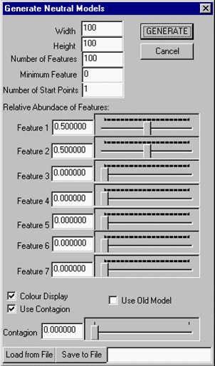
- The following are the constraints that can be used to express a neutral model:
- i) Width: The number of columns (cells per row) in the neutral model raster.
- ii) Height: The number of rows (cells per column) in the neutral model raster.
- iii) Number of Features: The maximum number of features (landscape element types) that may occur in an instance.
- iv) Minimum Feature: The numeric value of the first feature in the model (generally 0 or 1).
- v) Number of Start Points: This option is used in conjunction with contagion. It specifies the number of locations that are to be independently chosen (i.e. without using contagion). It must be at least one, but may be any number. These points are selected randomly in the output map. The remaining cells are produced using the influence of contagion from previously computed cell values.
- vi) Relative Abundance of Features: The relative abundance (i.e. relative probability) of each of the first seven features. These represent the expected relative occurrence of each feature in the landscape. Where contagion is used (especially high values of contagion), the actual abundance may be quite different. In this situation, these represent the expected relative occurrence of each feature over all instances of the model. Note that the relative abundance specified for feature 7 applies to all features greater than 7 (i.e. it applies to features in the range [7, Number of Features].
- vii) Colour Display: If selected, then instances will be displayed in colour. Otherwise they will be displayed in black and white.
- viii) Use Contagion: If selected, then contagion is used when model instances are generated. Contagion represents the degree to which features in the landscape are grouped together. A contagion value of 0 means no contagion (i.e. adjacency of features is random), while a value of 1 means that the probability of an adjacent cell having the same value is 1. Values of contagion between zero and one create varying degrees of "clumped" or spatially autocorrelated patterns. Negative contagion causes features of the same value to occur further apart than at random, where a value of -1 indicates that the probability of two adjacent cells holding the same feature is 0. Note that for extreme values of contagion (near -1 or 1), it may not be possible to simultaneously satisfy both the contagion constraints and the relative abundance constraints. We have proven a theorem that provides a method of coming as close as possible to satisfying both sets of constraints.
- ix)Contagion: The value of contagion to use. Currently, the value can only be in the range [0,1].
- x) Use Old Model: If selected, produce model instances using an older algorithm. The older algorithm exhibits a "stripping" bias when high levels of contagion are specified.
- xi) Load from File/Save to File: Load model parameters from or save to the file specified in the adjacent text box. These files generally should have a .nm suffix. It is useful to load pre-existing model files, modify them to suit the current needs and then save these to a new file. These neutral model files can be opened directly using the Open menu item in the Files menu described in section II.
